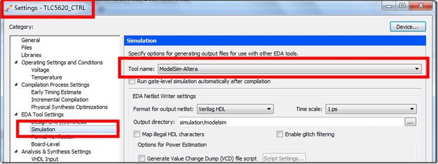
Step 8: In Quartus II, Ctrl+k (analysis and synthesis). Step 6: Set device to Cyclone V - 5CEBA4F23C7 (FPGA chip in DE0-CV board). The sw_led_tb.v is just for simulation with ModelSim).

Step 5: Add files sw_led.v (only sw_led.v. Step 4: Set the name of the project to sw_led. Step 3: Set working directory to D:\CSLW. Step 2: In Quartus II, File - New Project Wizard. Question 2: Explain why led = led (in red color) and led = led (in yellow color). Step 12: Select Wave window and adjust the waveform, you can see the waveforms as below. Step 9: In ModelSim, Simulate work.sw_led_tb. Vlog -reportprogress 300 -work work D:/CSLW/sw_led_tb.v Step 8: In ModelSim, Compile sw_led_tb.v. Step 7: Similarly, create a file sw_led_tb.v (Test Bench - for simulation) and add the following Verilog HDL codes to it. If you don't found Transcript window, click View - Transcript. Vlog -reportprogress 300 -work work D:/CSLW/sw_led.v Step 6: In ModelSim, Compile sw_led.v click Yes to create "work" library.

Step 5: In ModelSim, Control_S, save to sw_led.v. Step 4: In ModelSim, File - New - Source - Verilog and add the following Verilog HDL codes to edit window (Do NOT use Japanese). Step 3: In ModelSim, File - Change Directory to D:\CSLW. Step 1: Create a folder D:\CSLW (Do NOT use Japanese in the folder path).

If Altera Quartus II 13.1 was not installed on your PC, please download and install it on your PC. Design the following circuit in Verilog HDL and implement it on DE0-CV FPGA board.


 0 kommentar(er)
